


![]()
Repair
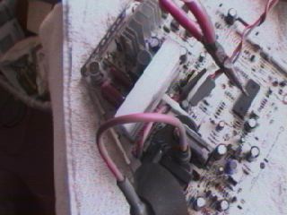
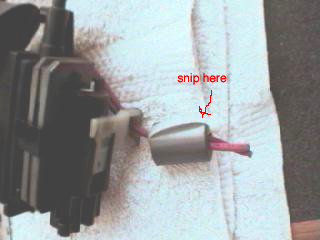
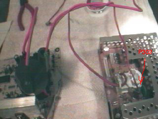
16. Isolate the analog board by clipping the two red wires that connect it to the video board. Cut them close to the FBT so you have some extra to work with when it comes time to connect the new FBT to the video board.
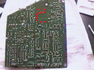
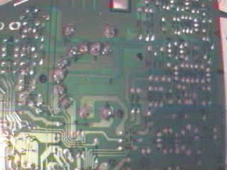
17. Turn the analog board over and desolder the twelve points (marked in picture) that connect it to the board. Desolder each point separately by putting a dab of solder flux on the solder, then lay the solder wick on top of the flux and press firmly with the tip of a hot soldering iron (don’t lean on the board too much, you don’t want to bend the parts underneath it). You should observe the solder flow up the wick by capillary action, leaving a clean post and hole. You may have to repeat the process two or three times to get all the solder out. Clip off the wick that is saturated with solder before moving on to the next point. Here is a link to another explanation of soldering.
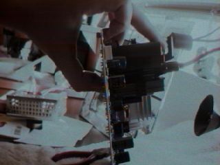
18. Be sure you have removed all the solder from each post and hole. Pull the FBT off of the board. If you get a lot of resistance, check again to be sure you don’t have any connections still soldered. If you rip it off the board with connections still soldered you will likely damage the board.
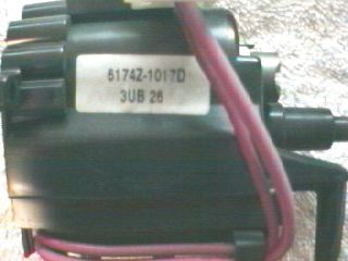
18B. Get the part number off of the FBT, it SHOULD start with 6174Z followed by 1017D for the Rev2 board and 1003G for the Rev1 board. You will need this number to find the correct replacement. Don’t bother with the other numbers on the FBT (3UB 26 in the picture), they are likely a lot or batch number. I find the best place to get a replacement is at either NEIparts or Nikko Electronics. Both sites have a search by part number option, try searching for just 6174Z and find the correct one in the results list. If you happen to have a FBT number that I did not list, they likely carry it as well. Check both sites for the best price. Nikko Electronics is in the U.K. so you may have to convert their prices from pounds to dollars (or whatever your currency is) and you have to add £6 for shipping to the US. Generally Nikko Electronics is cheaper, unless NEIparts has their version of the 6174Z-1003G FBT (called 6174Z-1003G-RP) in stock, which is cheaper and works just as good as the regular 6174Z-1003G (I’ve used both).
19. Remove the ferrite ring from the old FBT by clipping the zip-tie that holds it in place. If your old FBT doesn’t have a ferrite ring then don’t worry about it. It wouldn’t hurt to get one though.
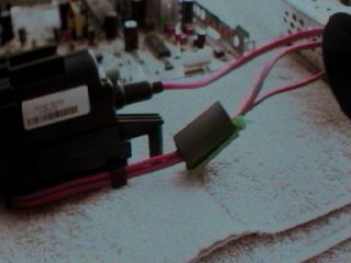
20. Thread the two long red wires from the new FBT through the ferrite ring and slide the ring close to the FBT. Thread a zip-tie through the ring as well, then use it to secure the ring to the wires. Make sure the wires are between the zip-tie and the ring to secure the ring in place. The ferrite ring reduces electromagnetic interference so you want to move it from the old FBT to the new one. If the new FBT already has a ferrite ring, there’s no need to replace it with the ring from the old FBT.
21. Align the posts of the new FBT in the holes of the analog board. It can only line up in one orientation. Don’t force it. Sometimes the posts on the FBT are slightly bent or misaligned. This will be obvious because you will not be able to get all the posts through the holes. If this is the case, it is OK to use a pair of needle nose pliers to gently bend the posts into alignment.
22. Flip the analog board over so that it leans on the FBT (make sure FBT is still in place). Solder the twelve connections. I recommend soldering two points that are far apart to secure the FBT in place while you finish the other ten points. You want the FBT to sit flush against the analog board. If this is not the case after soldering the first two points, desolder as necessary and push the FBT back in place against the board. IMPORTANT: When soldering (and desoldering if necessary), it is important to work quickly on each connection. You do not want to touch the soldering iron to any of the FBT posts for a long period of time or you may overheat the fine, thinly-insulated wires inside the component and short it out. It should not take longer than ten seconds to solder one connection. Take your time between soldering points, but solder each point as quickly as possible.
23. Disconnect the old P302 plug from the video board and connect the plug from the new FBT. If your new FBT doesn’t have a plug on it, use the old one and solder a connection to the skinny red wire.
24. Now you need to connect the thick red wire from the new FBT to the thick red wire that comes off the white plug on the video board. Clip the wires so they are a comfortable distance from both the FBT and the video board, but be sure to leave some overlap. It is better to have too much wire (you can tuck it in later if necessary) than too little. Strip about 1/2 an inch of insulation from the end of each wire. Twist the ends together and solder them as well. You don’t want a poor connection here so it is important to solder instead of just relying on the wires being twisted together. Cover the bare wires and solder with some electrical tape.