


![]()
Logic Board
Word of caution: the back of the logic board contains several chips. One of these chips needs cooling and thus it's recommended that a tiny heat sink be mounted on the large "Philips" chip (lower left in the photo). It's clearly marked, and if you happen to pull the logic board out of your own G4 case, you'll see the small aluminum block on the door of the chassis. You must use caution when installing the logic board not to damage any of these chips. In order to cool this properly, you might look at a local computer store and see if they have any bad motherboards around. The small heat sink found on the a typical 440BX chipset's northbridge is sufficient.
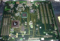
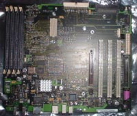
Above you'll see the back side of the G4 gigabit logic board, and below the top. The photos further down the page focus on various areas of the board that are important, going in a clockwise direction.
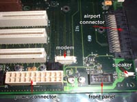
Starting at the upper right of the picture above we have the Airport card connector, the speaker, front panel, modem, and ATX connector. The G4 modem is just a little card which has one connector that snaps into the white connector.
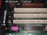
Next we have the main hard drive IDE connector, the battery, CUDA switch, and the 3 PCI slots and AGP slot with +28v Apple Display Connector power feed.
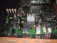
The ports from left to right: 2xFirewire, NIC, 2xUSB, audio in and audio out. The small heat sink in the photo is the gigabit networking controller.
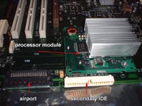
Finally, the area around the CPU mating connector: processor module, secondary IDE connector (for CD-ROM/DVD/ZIP) and, once again, the Airport connector.
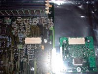
The logic board and CPU modules have a single white connector which is keyed to fit one direction. This allows one to upgrade from a single CPU to a dual CPU module on the same logic board.
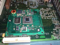
The CPU module shown installed without the heat sink attached for illustrative purposes.
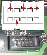
If you are using a PC case, make note of the following diagram. This is used to hook the LED/power buttons from the PC case to the G4 logic board. You'll need to separate all the ground leads from the front panel LED and switches on your case (most new ones are made this way now; older ones had the pairs of wires joined with a black plastic connector). Then, going up about 4-5" from the connector on each wire, snip all the grounds coming from the power, LED, and, reset switch lead. Splice them together using one of the leads so that you can connect them to the common ground, pin #2 on the bottom row. The remaining leads go from left to right on the top row: LED, blank, power, reset, and, programmer's reset (you'll need to obtain another small switch from Radio Shack if you wish to use this since PC cases only have the power and reset switch).
-
Main project page.
-
Places to obtain parts.
-
Brief look at the various models of G4 Power Macs.
-
Processor module and heat sink fabrication.
-
Quick look at the logic board.
-
Installing the parts in the case.
Final page: Installation of components in your case.
Prior page: The CPU module and heat sink installation.
![]()